Standardised Speed Distributions – Turning Radii
PJA’s latest technical blog focuses on the use of speed distributions for different turning radii in microsimulation models. This follows on from the previous Dynamic Assignment, Convergence and Speed Distributions topics.
As with all of our technical posts, we acknowledge that these are not ‘set-in-stone’ methodologies and other techniques and processes may exist. However, we want to share our current processes to encourage feedback and improvement, as well as providing some guidance for those looking for a starting point on specific modelling methodologies.
This post focuses on the need to consider appropriate reduced speed areas for turns and then their associated speeds when developing microsimulation models.
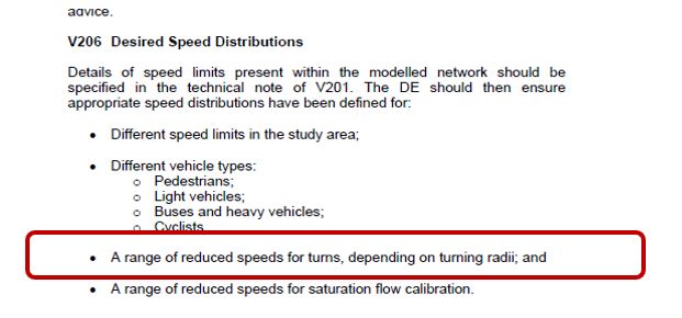
Transport for London’s (TfL) Modelling Guidelines suggest that speed distributions used for turns should be dependent on the turning radii (see figure below).
Whilst the DfT and TfL free flow speed distributions can be utilised, we have reviewed other guidance to understand if there are other means of calculated more appropriate speeds for turning radii.
Our research led us to two main sources – Design Manual for Roads and Bridges (DMRB) and the Chartered Institute of Highways & Transportation’s (CIHT) Manual for Streets 2. From these documents, we followed two main steps.
**It is acknowledged that the DMRB has recently been updated and the new documents are now available online. However for the purposes of this blog post, reference is made to the previous TD 42/95. A review of the new documentation and any associated update to this post will follow in due course.**
Step 1 – Minimum Corner Radii identified from DMRB
TD42/95 from the DMRB suggests that the following radii should be a minimum for large goods vehicles for turning manoeuvres at junctions. We based our calculations on a large goods vehicle as this would provide a worst case for the road network modelled.
| Simple Junction - Urban Area - No HGV provision = | 6 | m |
| Simple Junction - Rural Area - No HGV provision = | 10 | m |
| Simple Junction - Urban Area - With HGV provision = | 10 | m |
| Simple Junction - Rural Area - With HGV provision = | 15 | m |
| Ghost Island Junction - With HGV provision = | 15 | m |
| Staggered Junction - With HGV provision = | 15 | m |
| All other circumstances = | 20 | m |
From these figures, we were able to determine that for different junction types, the highest braking / lowest speed distributions would be required for radii between 6m and 20m.
Step 2 – Calculate Design Speeds for Minimum Corner Radii
From Chapter 8.3 of Manual for Streets 2, design speeds were determined for the minimum corner radii derived from TD42/95.

Therefore, applying the V²/R value of 56 to the minimum corner radii from TD42/95, the following design speeds have been determined
| Speed | Radius (m) | |||||||||||||
| 6 | 10 | 15 | 20 | 25 | 30 | 35 | 40 | 45 | 50 | 55 | 60 | 65 | 70 | |
| kph | 18.33 | 23.66 | 28.98 | 33.47 | 37.42 | 40.99 | 44.27 | 47.33 | 50.20 | 52.92 | 55.50 | 57.97 | 60.33 | 62.61 |
| mph | 11.39 | 14.71 | 18.01 | 20.80 | 23.25 | 25.47 | 27.51 | 29.41 | 31.19 | 32.88 | 34.49 | 36.02 | 37.49 | 38.91 |
[Additional radii have been included to determine design speeds for other corner-speed profiles]
To fit in with our Standard VISSIM Template, corner desired speed distributions were split into three categories – Low Braking, Medium Braking and High Braking.
As a result, the following split of the results above have been chosen.

These speed distributions formed the basis of the turning radii speeds included within the VISSIM model and allowed individual turns measured (e.g. from OS Mapping in DWG format) to be assigned to an appropriate speed profile.
Final Comments
The use of the DMRB and Manual for Streets 2 Guidance has allowed PJA to develop an evidenced methodology in determining appropriate speed distributions for the associated turning radii.
It is acknowledged that this is not the only methodology available for identifying suitable speeds, but we feel it does provide a useful starting point in developing a base model for calibration and validation.
As with other modelling elements, the use of more local, site-specific data should always take president, if this data is available and able to be analysed appropriately.